
When we think of GPS-based instrument approaches, we usually lump all the approach minima into a single “GPS approach” bucket. We tend to mentally order the types with WAAS as better than non-WAAS, and vertical guidance better than those without. After all, that’s how the magic box picks the type of service to provide.
These are usually safe assumptions, but occasionally you’ll come across a procedure that turns them on their head. There are quite a few procedures that have lower non-precision LNAV minimums than vertically guided LNAV/VNAV minimums, and even some that have lower non-WAAS LNAV/VNAV minimums than WAAS LPV minimums. Since each type of GPS minima is evaluated independently, these instances indicate that there’s more going on in these procedures than meets the eye.
Currently available GPS procedures may have been developed under one of several obstacle evaluation standards since they first started appearing in 1994. The last major standards overhaul was in 2007 with the 8260.54A order, and the recent 8260.58 order didn’t change much.
TLAs (Three Letter Acronyms)
In order to fully understand the differences between the different types of GPS-based approaches, we must first delve into some TERPS concepts, perhaps a bit deeper than you might wish.
The fundamental concept behind instrument approaches is the required obstacle clearance (ROC). As you might have guessed, this is the minimum vertical separation between a given position and the nearest obstacle below. When certain criteria are met, such as the final segment being longer than 6nm or a remote altimeter being used, ROC may be increased beyond the standard.
So, ROC tells you how much clearance you need. Next, the obstacle evaluation area (OEA) tells you where you must have that clearance. The OEA defines the lateral boundaries of the protected airspace for an approach. Thus, the minimum altitudes of an approach are designed to meet the ROC within the OEA.
The OEA for each segment of an approach is further divided into a primary area down the middle of the approach course and identical but mirrored secondary areas on the left and right of the primary area. (RNP approaches, beyond our scope here, only have primary areas.) The primary area is considered the normal course width, with the secondary area protecting for “bad days.” Within the secondary areas, ROC typically tapers to zero at the outer edge.
Different approach segments have differing ROC values and OEA dimensions, as do the various final segment types (LNAV, LP, etc.). For instance, initial segments have a ROC of 1,000, a primary width of 2 nm from the centerline and a secondary width of 1 nm. However, the intermediate segment ROC is only 500 feet and has an OEA that tapers from the initial width to the final OEA width.
The result of providing the ROC within the OEA creates the obstacle clearance surface (OCS). The OCS can get lower as you get closer to the runway and towards the center of the approach course, thus giving it a three-dimensional shape. This is the case for approaches with vertical guidance. For en route, terminal and non-precision final segments, ROC is constant throughout the OEA, resulting in a flat OCS.
LNAV and LNAV/VNAV
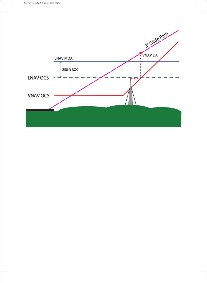
The LNAV approach is the most common GPS approach, and the only one whose minima apply to circling. Lacking vertical guidance, it has a flat OCS with a standard ROC of 250 feet (plus any adjustments). The LNAV’s OEA is depicted on this page. Within an LNAV final segment, full-scale lateral deflection of your CDI is at 0.3nm, half of the primary area, so there’s a lot of leeway.
LNAV/VNAV is the non-WAAS approach with vertical guidance, meaning it has protection between decision altitude and the runway through a Glidepath Qualification Surface. LNAV/VNAV approaches have the same lateral OEA and lateral CDI scaling as LNAV approaches, minimums as low as 250 feet, but have a unique OCS that is partially sloping and partially flat. The sloping portion of the OCS descends rapidly from the FAF (at a gradient of about 24:1 as opposed to 34:1 for ILS and LPV final segments), and continues to the runway at a height of 89 feet above the runway.
Once the LNAV/VNAV OCS with its larger ROC slopes lower than the flat LNAV OCS, it is possible that obstacles may penetrate the LNAV/VNAV OCS but not penetrate the LNAV flat OCS. If this happens, it can result in a higher LNAV/VNAV DA than the LNAV’s MDA. So, whenever you see an approach where this is true, chances are that it is a result of an obstacle fairly close to the runway which penetrates the LNAV/VNAV OCS, but isn’t high enough to penetrate the flat LNAV OCS.
Baro-VNAV
The reason the LNAV/VNAV OCS is so complex and limiting is because its origin lies in barometric vertical navigation (Baro-VNAV). Before we had WAAS, approaches flown using Baro-VNAV used the aircraft altimeter setting to compute a vertical path. Because the vertical flight path is dependent on an accurate altimeter setting on these approaches, remote altimeter settings are not permitted.
Additionally, since pressure altimeters are calibrated to standard conditions, any deviations from standard temperature result in an altimeter error proportional to the altitude. The LNAV/VNAV OCS must allow for these errors while providing required obstacle clearance.
Since a lower than standard temperature results in a lower true altitude than indicated, the steep LNAV/VNAV OCS is built to allow an extremely low temperature. This temperature is shown in the chart notes, and the procedure is not authorized at lower temperatures. Likewise, there is a high temperature limit, above which the procedure is not authorized, since the aircraft would be experiencing an excessively high descent rate.
With WAAS, LNAV/VNAV approaches are no longer barometrically aided, and therefore none of the restrictions discussed here apply when flown using WAAS. The temperature limitations can be disregarded, and procedures are permitted using remote altimeter sources. However, many FMS equipped aircraft are not capable of using WAAS and still rely on barometrically aided vertical navigation, so designing the procedures around their limitations is unlikely to change any time soon.
Who da Boss?
As discussed in “GPS Alphabet Soup” last month, a single GPS approach can have as many as four different minima. That’s unfortunate in a way, as we don’t get to choose the style of GPS approach we want to fly. We just select the procedure by name and the navigator will choose the “appropriate” type for us.
Today’s GPS navigation databases do not include any data about an approach’s MDA or DA, so the magic wonder box doesn’t know which approach will take you closest to the ground. Consequently, using the currently available satellite environment only, but not the minima, it has no way of selecting the optimum type. Therefore, it relies on the simple ordering and it will select an LNAV/VNAV, if present, over the LNAV even if the LNAV has lower minima.
It would be nice if pilots were able to choose to fly to the lower LNAV minimums when this happens, and thankfully, the FAA makes that possible. AIM 5-4-5 (i)(5) states that “[t]his should be a clear indication to the pilot that obstacles exist below the MDA which the pilot must see in order to ensure adequate clearance. In those cases, the glide path may be treated as a VDA and used to descend to the LNAV MDA as long as all the rules for a non-precision approach are applied at the MDA.”
So you may safely disregard an LNAV/VNAV annunciation and fly the approach to the LNAV MDA, treating a glidepath indication as if it were LNAV+V (for advisory use only). Of course, in this situation, never attempt to fly to LPV minimums. While these situations are certainly TERPS edge cases which highlight procedure design peculiarities (and sometimes defy logic), they should remind pilots that the standards applied to the various GPS minima are quite different.
Lee Smith, ATP, CFII, is an aviation consultant, flight instructor and Part 135 King Air pilot in Northern Virginia.


