
Flight-critical information for IFR flying includes attitude, heading, airspeed, and altitude. Navigation information is high on the needs list but is not as critical as the previous items. The same is true for communications. The criticality generally follows the doctrine of aviate, navigate, and then communicate. Likewise, the FAA system safety analysis (required for equipment certifications) places the highest criticality requirements on attitude, heading, airspeed and altitude.
Here, I’ll first explain how the flight-critical data is generated in today’s digitally integrated cockpits, possible failure modes, and then I will dig into possible propagation of a failure across other functions in an integrated system. Last, I will discuss recommendations for handling the situation.
Attitude
In today’s integrated systems, the attitude and heading information comes from an attitude heading reference system (AHRS). The AHRS incorporates three rate gyros and three accelerometers. This combination of rate gyros and accelerometers is considered an inertial measurement unit (IMU).
IMUs probably have the widest range of specifications (and prices) of any piece of avionics. The rate gyros and accelerometers range from very expensive and physically large ring laser gyros and precision accelerometers to low-cost micro-electro-mechanical-system (MEMS) gyros and accelerometers. What’s the difference? The expensive IMUs can provide attitude, heading and navigation data independently without updating or aid from supplementary sensors. They are accurate enough to fly across the Atlantic, unaided, and be within a few miles of the destination. Submarine IMUs are designed to go even longer without position updates.
On the other hand, the MEMS gyros and accelerometers commonly used in GA systems are much less accurate and do require “aiding” to obtain a usable attitude and heading. The physical size of the MEMS wafer is a determining factor in how accurate the device is. However, even the largest of the MEMS devices in an IMU cannot provide data accurate enough for navigation. Thus, they require “aiding” to provide attitude and heading information. MEMS devices can only provide attitude and heading information for short periods if the external aiding information is lost.
For attitude aiding, you need external supplemental information that provides acceleration/velocity information. An Air Data Computer (ADC) and/or GPS can provide the information to aid the MEMS solution. The actual “aiding” is done in Kalman Filters implemented in the AHRS microprocessor. The Kalman filter blends data from a sensor with good short-term accuracy with another that has good long-term accuracy. The short term is provided by the MEMS gyros and accelerometers and the long-term data is provided by the air data (pitot/static) and/or the GPS.
Using GPS offers an additional benefit in that it includes X, Y and Z axis accelerations and velocity that can be fed directly into the Kalman Filter. The AHRS is a “strap-down” IMU meaning the large gimbal mounts used in early inertial navigation systems like Litton’s LTN-51 are not required. The gyros and accelerometers are hard mounted (“strapped down”) inside the AHRS. The strap-down systems use mathematics instead of mechanical torque motors and gimbals as was done in stable platform systems such as the LTN-51. I won’t get into the mathematics but the course I took on the subject (Euler angles and body rates/axis transformations) wasn’t near as much fun as flying.
Heading
The heading is generated in the AHRS, similar to what was done for attitude. Again, supplemental (aiding) information is required for a usable heading. In this case, the supplemental information is from a magnetic field sensor. The spinning mass directional gyros (think Sperry C-14) used a flux valve for this purpose, but today’s AHRS use a magnetometer. The magnetometer serves the same purpose of providing the long term accurate magnetic heading but also aids the attitude calculation by detecting the magnetic field in three dimensions.
Airspeed and Altitude
Our December 2022 article “Unreliable Airspeed” describes in detail the implementation of airspeed and altitude measurements in today’s integrated cockpits. Briefly, airspeed comes from the pressure difference between what is sensed by the pitot tube and the static air pressure using a piezoresistive silicon sensing element. The resistance of the element changes as the differential pressure changes. This resistance change is converted digitally into indicated airspeed.
Altitude is measured solely from static port(s) pressure measurement. This pressure sensor must be more precise (better calibration in production) than the one used for airspeed measurement. While it wasn’t always true, these silicon sensors can now be used across the board for airspeed and altitude measurements and can even meet the increased precision requirements of Reduced Vertical Separation Minimum (RVSM) systems.
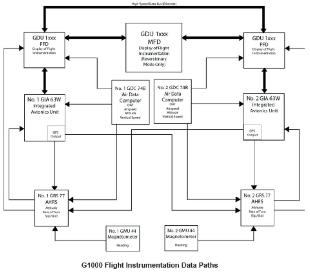
System Block Diagram
You can learn a lot by looking at the avionics-system block diagram and asking questions. Let’s look at the Garmin’s G1000 flight instruments block diagram. First, look at the AHRS since it generates half of the flight-critical data. What are the inputs? First is the magnetometer, as expected.
You’ll also notice a GPS input from both the on-side and off-side Integrated Avionics Computer and an input from the on-side Air Data Computer (ADC). This is interesting since the GPS is the best at aiding a MEMS solution, so why is the air data input there, especially since there are two GPS inputs?
Good question and one I asked of Garmin’s Bill Stone, Senior Business Development Manager. He said: “The AHRS sensors in the G1000 and our other integrated systems utilize three independent sources of overlapping data for aiding and monitoring the MEMS sensors in the AHRS; GPS data, air data, and 3D magnetometry. This provides a robust, high-integrity and fault-tolerant solution. Loss of any one of those sensor inputs does not result in degraded attitude determination.” He added that the AHRS would use the ADC information if the aircraft was in a GPS-denied-service area.
What Can Go Wrong?
Use the block diagram to ask yourself what happens if one of the AHRS inputs is lost. Since the GPS inputs to the AHRS are redundant, there shouldn’t be an issue of losing the GPS velocity information required for aiding. However, suppose you don’t have the redundancy provided by the G1000 and only have one GPS and no other velocity information source going into your AHRS. If you lose the single GPS, then you will also lose all attitude and heading information.
Dual GPS inputs will normally provide the necessary redundancy, but what happens if the GPS signals are disrupted such as what happened near Dallas Fort Worth Airport on October 17-18, 2022? The G1000 handles this situation by also providing the air data input. However, a few avionics systems don’t use GPS aiding but rely solely on the ADC.
If your block diagram doesn’t show a GPS input to the AHRS but just a single ADC, you could be in for a surprise if the air data computer fails. In this case, if the ADC fails, you have lost all flight critical information. There is no attitude, heading, airspeed, altitude or vertical speed. You’ll need to use the standby instruments.
What can cause loss of air data? The microcontroller in the ADC could go belly up, but at least that provides a “flag” to alert you there is an issue. A more dangerous failure not normally flagged is a blocked pneumatic (pitot or static) line. It is difficult for the avionics to detect a blocked pressure line. While it is easy for the avionics to check that the ADC microprocessor is working, and if the pitot heater is working, checking for a blockage is not. The best the avionics can normally do is check if the pressure is outside the nominal range. For aiding the MEMS solution, a better combination would be to use both a GPS and an air data input for aiding as is done in the G1000.
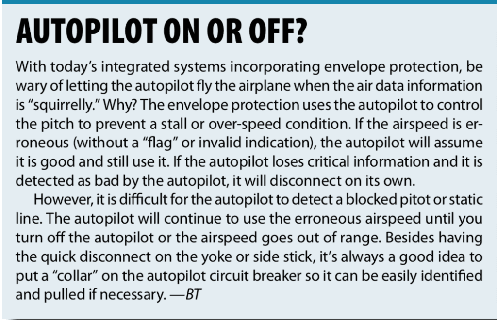
With today’s integrated avionics a blocked pitot tube can affect more than just the displayed airspeed. Several manufacturers have integrated envelope protection built into their systems. If the system detects an airspeed that requires stiffening the pitch-feel or pushing the nose down to prevent stalling or pitching up to prevent overspeed the system will do that. It’s fine normally, but it isn’t when you have an air data “plumbing” issue. You really have to be on top of your game when the autopilot decides it knows best and takes control.
Besides envelope protection issues, illogical failures of the primary flight display (PFD) have also been reported with pitot static failures (see “Ice Is Not Nice’ by Fred Simonds in the January 2022 issue of IFR Magazine).
What Do I Do Now?
If you get into that uh-oh moment, when nothing makes sense, there is a lot to think about in short order. Determining what information is correct and what is erroneous will require good system knowledge and keeping up your scan.
There have been many accidents caused by incorrect airspeed information due to an iced-over pitot including the Northwest B727 accident where the three-man flight crew fixated on the increasing airspeed as they climbed. They ignored the pitch attitude and kept pitching up to reduce the erroneous airspeed until they stalled the aircraft. More recently, the Air France 447 crash in 2009 was started by iced-over pitot tubes.
In that moment, don’t jump to conclusions or fixate on one instrument. What other information can you use to determine what is false and what is true? An angle of attack indicator (sensor-based, not derived) is worth its weight in gold in this situation. You should also know, from memory, the proper pitch and power for that phase of flight whether it is climb, cruise or approach. You should then check the current pitch and power versus what is displayed on the air-data instruments.
Unless you have already gotten into an unusual attitude, don’t get wild with pitch or power changes beyond what is normal for that phase of flight. If you have visual conditions stay there. Check the horizon on the windscreen and set your power accordingly.
You need to be on top of the situation quickly in instrument conditions, but do not get fixated on only one instrument and immediately check the pitch on the standby attitude indicator. If pitch is where it should be and isn’t changing and the airspeed is going crazy up or down, it’s a good bet you have a pitot problem.
Again, check or set the pitch and power appropriate for that phase of flight. Note that the standby airspeed indicator and altimeter are usually plumbed to the same pitot and static ports as the primary, so there is little help there if you have a blocked pitot or static line. However, check your block diagram or talk to your mechanic to determine if this is true for your aircraft.
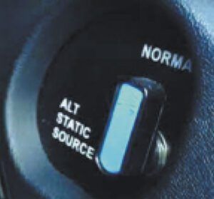
With a plugged static line, in a non-pressurized aircraft, you can switch to the alternate static source that vents to the cabin. If you are flying a pressurized aircraft, the alternate static inlet will typically be located in a non-pressurized area of the aircraft, such as in the nose forward of the pressure bulkhead, or the aft fuselage. In either case, there will be some error in the altitude due to the difference between the inside cabin pressure and the outside pressure, but it should be manageable.
Having erroneous airspeed and altitude and possibly losing the attitude information is a serious situation. If you’re in IMC, ask ATC for vectors to VMC. Even if you are in VMC you can easily lose orientation at night in remote areas with limited lights on the ground or over a large body of water. You might think you’re fine, able to fly using the standby instruments, but an upset or turbulence can make things very demanding and having a good visual reference helps immensely. ATC can help vector you to VMC. Don’t be bashful, this is the time to declare an emergency.
Epilogue
More now than ever it is imperative to study and understand the systems, whether flying an old C 172 or a Cirrus Vision Jet. Ask yourself what can go wrong and prepare for it. Murphy said whatever can go wrong, will go wrong and remember he was an optimist. Also learn from the mistakes of others; you don’t have enough time to “discover” them all yourself.
Bob Teter is a retired CFI with a 43-year career in avionics development, primarily for business jets. His 1200 hours as PIC were all hand flown because he could never afford an aircraft with an autopilot. He currently resides in Pennsylvania and does freelance writing and avionics consulting.


Hi there, great article! I was wondering if we can debate the accuracy of this G1000 instrumentation diagram. The G1000NXI / G1000 diagram in Garmin’s manual shows 1 ADC, 1 AHRS, and 1 Magnetometer unit, and the diagram in this article shows 2 of each. Can you elaborate, please?
1 of each is the minimum, but 2 of each are supported, it depends on how each airframe manufacturer designs their install and what you order. A Bonanza I flew had 1 each of ADC and magnetometer, but had dual AHRS. Another Bonanza had 1 megmetometer but dual integrated ADAHRS (ADC and AHRS integrated into one box).
Thanks for the question. The block diagram can be found by googling “Garmin G1000 System Maintenance Manual 190-00903-00.” The block diagram is then on page 2-3, and it was Rev. A. This installation is typical for a Light Jet (LJ) or Very Light Jet (VLJ). The system can be configured with less sensors than shown in the block diagram in the article, but consequently it will have less redundancy than the “full up” system.