
In July 2013, we published “GPS Alphabet Soup” covering the five types of GPS approaches in some depth. A reader suggested a follow-on article with a table that gathers all the approach types and their key characteristics in one place. That seemed like a fine idea and it also affords us the opportunity to share some additional information.
Precision vs. Nonprecision
Let’s get this cleared up right away. The official definition of a precision approach is different than the practical one. Officially, only an ILS is a precision approach. “Precision approach” is defined by ICAO in terms of the components of an ILS. To further muddy the waters, certain GPS LPV approaches can achieve a higher precision than an ILS. So, officially a “precision” approach has nothing to do with its precision. OK?
A more practical definition of “precision approach” is one with designed, surveyed vertical guidance to a decision altitude. This practical definition is partly accepted in the instrument Practical Test Standards—an LPV satisfies the requirement for a precision approach, just like an ILS.
Clearly, another term is needed here. That term is “APproach with Vertical guidance'” Think of an APV as a precision approach from a practical standpoint. The table below tells us if the approach is a NonPrecision Approach (NPA) or precision (including APV).
The LNAV+V is a hybrid. Its advisory glidepath is a mathematical construct, not a surveyed part of the approach design. Since they’re not designed approaches, there are no LNAV+V minimums; we use simple LNAV minimums.
All GPS approaches with a glidepath, including the LNAV+V, require WAAS.
Linear vs. Angular Deviation
Course guidance requires explanation. The difference between linear and angular deviation affects the accuracy of approaches and how we fly them.
Remember that first ILS when you were 100 feet above DA and you sneezed? That momentary lack of attention caused the needles to peg faster than your instructor could utter, “Gesundheit.” But if that same sneeze occurred outside the marker, the needles remained centered. That’s angular course guidance.
The angular course deviation indication displays degrees off course. The distance off course for a given indication decreases as you get closer to the source.
Ground-based navigation (ILS, LOC, VOR) inherently provides angular deviation. However, the GPS receiver inside your navigator just calculates your position and how far that position is from a desired course.
When you punch in Direct-To on the navigator, your distance off course is displayed as a uniform deflection of the CDI. If you’re 463.7 miles from your destination, two miles off course will have the same two-dot needle deflection as when you’re one mile from your destination. That’s linear deviation.
This enroute linear deviation doesn’t serve us well on an approach. Thus, LNAV, the first GPS approach, simply increases the sensitivity to 0.3 nautical miles full-scale, but it’s still linear.
With LP and LPV approaches, your navigator converts the internal distance off course into an angular deviation indication. In fact, by design, the behavior of your CDI on an LP or LPV approach mimics that of a LOC or ILS approach. This angular deviation presentation enhances the precision available to us when flying these approaches.
Using the practical definitions, nonprecision minimums are expressed in terms of minimum descent altitude, MDA, and precision approaches have decision altitudes, DAs. Thus, you can tell instantly if the approach is precision or nonprecision—whether it was designed with a designated, surveyed glidepath. (Again, note that the LNAV+V and the upcoming LP+V are mathematical constructs for reference that aren’t part of a surveyed, designed glidepath. These only provide safe vertical information above the nonprecision MDA.)
Vertical Guidance
As discussed, it takes surveyed, designed vertical guidance to make a precision or APV approach. Before GPS, that meant an ILS. With the advent of GPS but before WAAS, a glidepath using barometric pressure enabled the first LNAV/VNAV approach. Baro-aiding uses pressure altitude corrected for local barometric pressure, not GPS altitude, to provide a glidepath.
In July 2003, the introduction of WAAS with its tighter integrity limits allowed GPS developers to construct a glidepath based on GPS altitude, obsoleting baro-aiding. Baro-aiding remains legal and you will see it referenced in approach notes where LNAV/VNAV approach minimums are published.
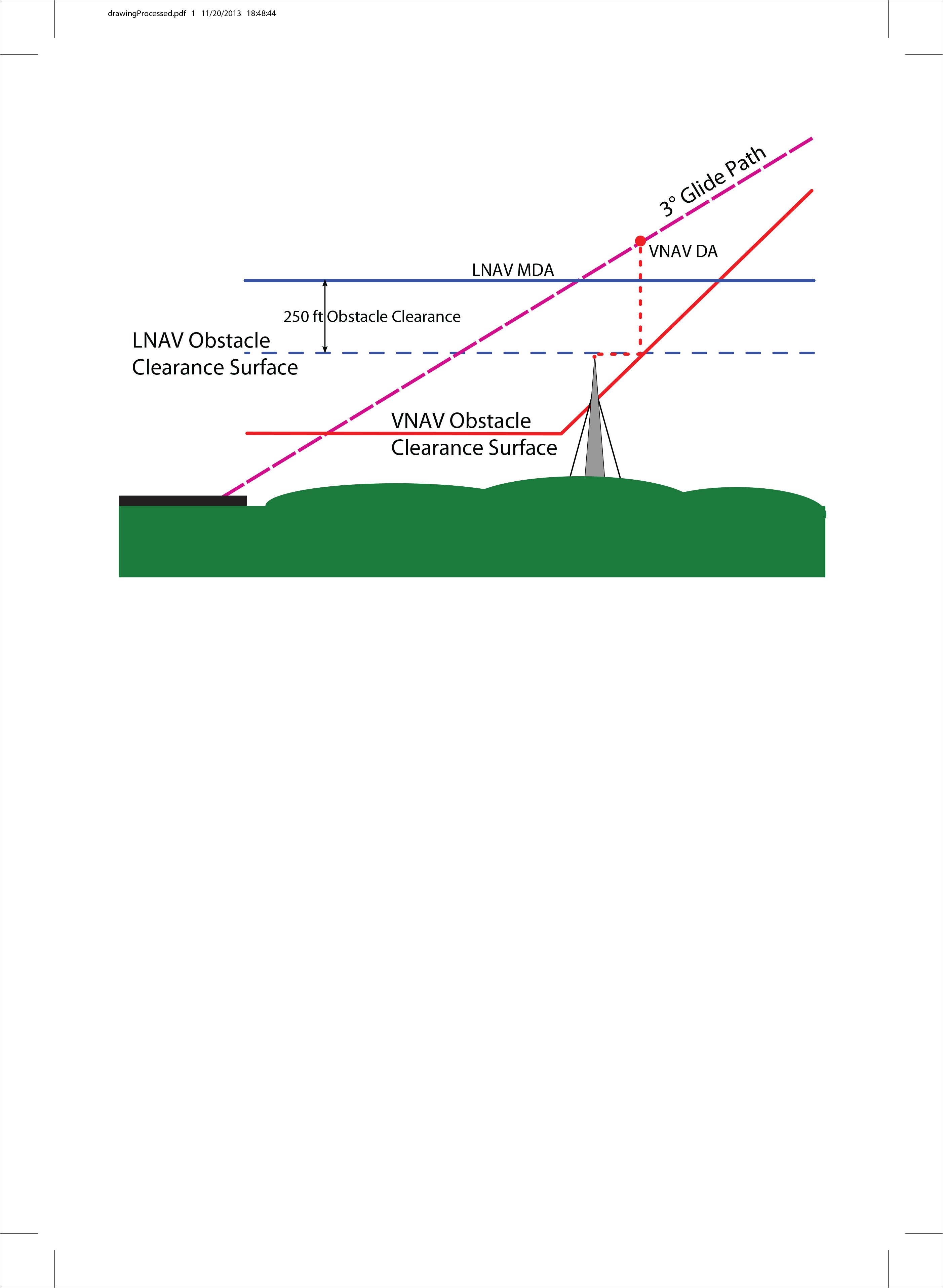
Sometimes a nonprecision LNAV approach can take you lower than a precision LNAV/VNAV because of possible obstacles and the differing clearance requirements for each approach type. This was discussed in depth in Lee Smith’s excellent IFR Clinic article, “Obstacle Clearance” in August 2013.
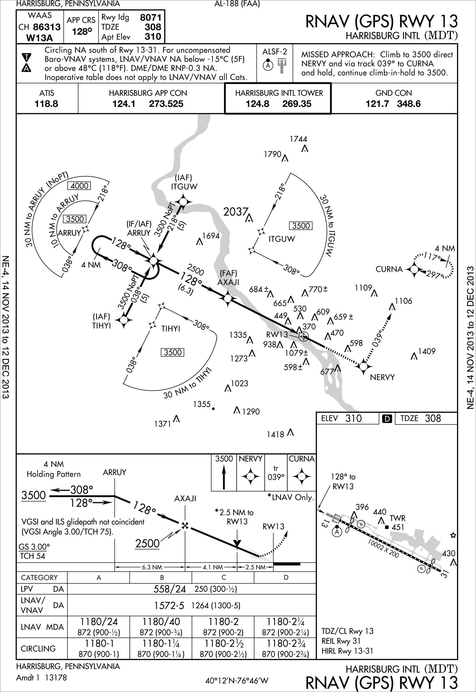
Look at the RNAV (GPS) RWY 13 at Harrisburg International. The LNAV/VNAV minimums are a whopping 1572 feet and five mile visibility. Notice the 1079-foot obstacle just before and right of the runway, requiring the higher minimums.
TERPS requires that the circling altitude be no lower than the associated nonprecision MDA, the LNAV with its 1180-foot MDA, here. Note also that there’s just one set of circling minimums showing the circling MDA by aircraft category, not one line per approach type.
The U.S. Aeronautical Charting Forum is a government and industry group that makes recommendations to FAA. They recommended that the LNAV/VNAV procedure be published separately with its own chart showing circling minimums no lower than the LNAV/VNAV DA when the LNAV/VNAV DA is higher than the LNAV MDA.
With the LNAV going lower than the LNAV/VNAV at Harrisburg, as it does at many airports, you wonder why the LNAV/VNAV procedure exists at all. Addressing this, the Forum recommended that when the LNAV/VNAV minimums are 60 or more feet higher than the associated LNAV, the LNAV/VNAV procedure be scrapped.
The FAA has thus far declined these recommendations from the Forum. Not only are LNAV/VNAV approaches not disappearing, they are growing apace with new LPVs.
The ILS
By the numbers, the 3341 LPV approaches dwarf the 1100 civilian ILSes in the U.S. There is little difference in the performance of an LPV from that of an ILS. The obstacle evaluation area for an LPV is identical to that for an ILS approach, with minimums and site requirements also the same.
An ILS has four components: localizer and glideslope transmitters, marker beacons and an approach light system. In recent years, many compass locators and marker beacons have been decommissioned or allowed to fail and not be replaced on Cat I approaches.
The glideslope transmitter is only five watts and normally has a 10 nm range. Its beam projects between 2.5 degrees and 3.5 degrees above horizontal, reaching about 1400 feet AGL at the FAF, creating a thin, accurate glidepath of about 1.4 degrees. The beam can be raised to 4 degrees if conditions warrant. The glideslope beam has no back course. Because the beam can be unreliable below DH, visual references should be used as well. The beam is usable to the runway threshold if no DH is published. Flight Standards doesn’t normally flight inspect CAT I ILSes below 100 feet AGL.
Although still the gold standard, the ILS does have its issues.
The position of the glideslope receiver antenna on the airplane is significant, since it’s that location that is providing vertical guidance. Thus, if the antenna is high on the tail, the landing gear can be much lower on larger aircraft, possibly causing some abrupt arrivals.
Another potential issue is that when approaching glidepath intercept from above, you may receive false courses and reverse sensing at angles much greater than the published path.
Localizer and glideslope signals can be affected by reflections caused by surface vehicles or aircraft near the antenna. For this reason, ILS Critical Areas are established and when weather is below 800-2, towers keep these areas clear. Plus, aircraft are not permitted to hold below 5,000 feet between the FAF and the airport to avoid localizer variations.
WAAS calls for a loss of signal integrity alarm in 6.2 seconds, but ILS monitors won’t trigger a signal anoaly until 10 to 12 seconds, a difference that can matter.
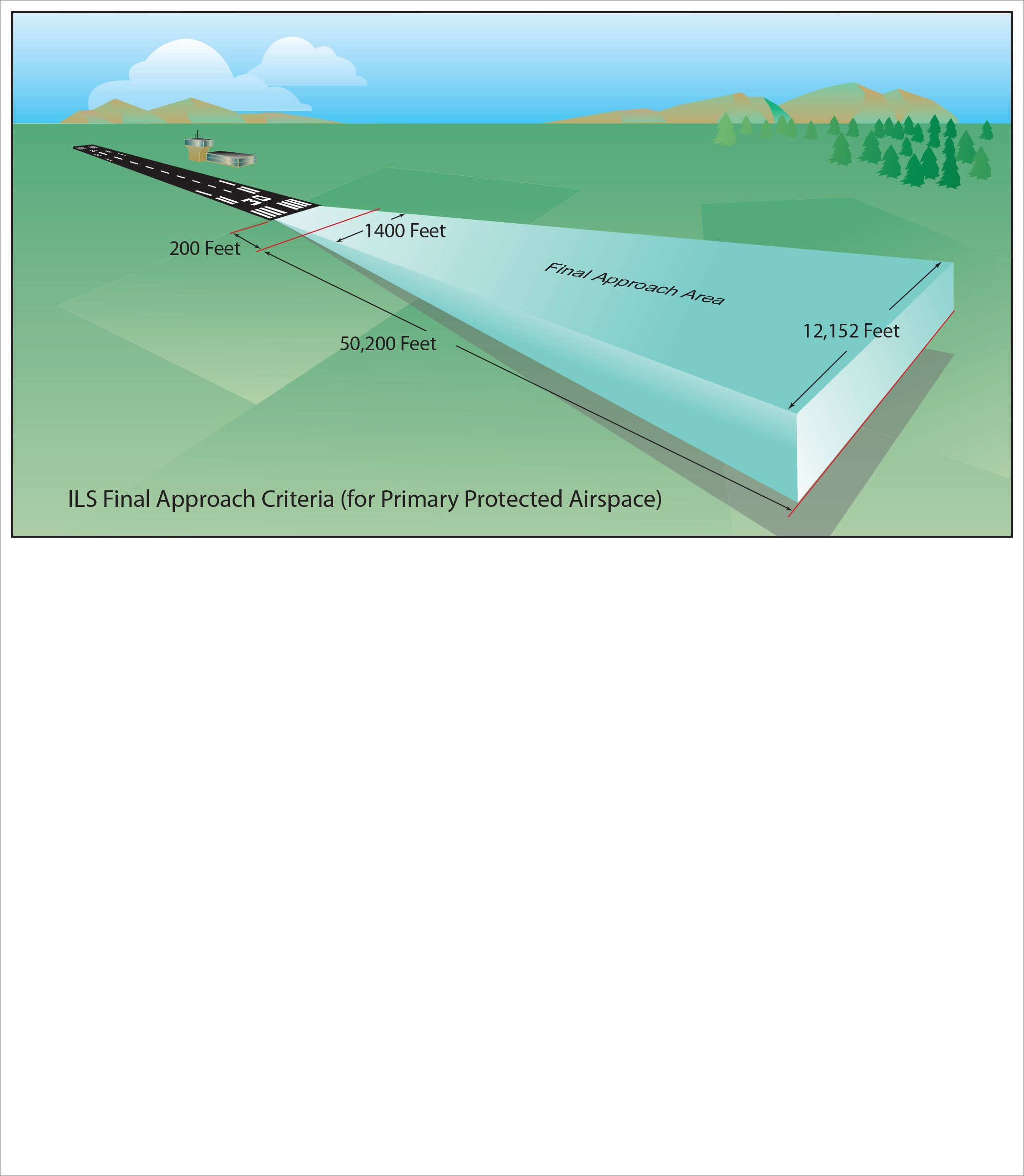
Localizers provide the lateral guidance of an ILS and they can also be installed stand-alone, without the glideslope. Localizers offer narrow and precise angular course guidance of 2.5 degrees, translating to 700 feet either side of centerline at the missed approach point. The localizer beam must track within three degrees of the runway centerline (or else it’s called a localizer-type directional aid, LDA) and is surveyed to provide at least 250 feet of obstacle clearance in the final approach area.
With transmitting power around 100 watts, the localizer can be received up to 18 nm away if you’re at least 1000 feet above the highest terrain and within 10 degrees of the course line, or within 35 degrees at ten nm. Its service volume reaches 4500 feet AGL over the transmitter. This range can be handy to find your way to an airport even without an approach. Some localizers have a radiation lobe out the back to form a published backcourse localizer approach.
VOR Approaches
The VOR approach is the only ground-based approach where the navaid can be behind you. VOR approaches have endless variants, such as VOR on/off the field, FAF or no FAF, circling only, VOR/DMEs, stepdown fixes, DME arcs, etc.
The obstacle evaluation area in the final approach segment starts at the final approach fix and ends at the runway or missed approach point, whichever is encountered last. It’s part of an amazingly lengthy 30 nm-long trapezoid with customary primary and secondary areas.
Centered on the final approach course, the primary area is two nm wide at the VOR, expanding to 5 nm wide 30 nm away. A secondary area on each side of the primary area starts at zero nm wide at the facility and expands to 1 nm each side of the primary area 30 nm away.
For straight-in landings, the minimum obstacle clearance in the primary area is 250 feet. In the secondary area, 250 feet of clearance at the inner edge tapers to zero at the outer edge.
Optimum length of the VOR final approach segment is 5 nm, stretching to a maximum of 10 nm. The minimum length must be large enough for an aircraft to make the required descent and regain course alignment when a turn is required over the facility.
All these approaches offer great operational diversity and the chance to have some fun. Go fly a few!


