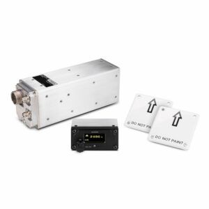
Before we dig into this topic, we need to define some terms. Recall your private ground school where they talked about the different types of altitude measurement? Absolute altitude was one, and it’s the actual distance the aircraft is above the ground at any point, as if you stopped midair and extended a tape measure out the window. Once a popular retrofit in piston singles like Bonanzas and Mooneys, these are now typically only found in far more complex aircraft.
There are two techniques used to measure that absolute altitude. One is properly called a radio altimeter and the other is a radar altimeter. (More below.) The terms are often conflated, so we’ll just use the generic term rad alt when talking about the hardware, and abs alt when talking about the measurement they report.
Rad alts and potential interference from the 5G transmissions from cell towers have been all over the news. On one side, the telecommunications industry paid billions of dollars for the rights to use those frequencies. On the other side are the airlines and other operators who have been using rad alts in safety-critical applications for decades.
Abs Alt is Useful
Rad alts are the only instruments that directly measure the aircraft’s height above the ground (AGL)—its absolute altitude. The height above ground information is available in the cockpit as “raw data” on a rad alt, but that data might also be used by other systems on the aircraft. Other altimeter systems (barometric pressure or GNSS altitude) can infer or calculate the distance from the aircraft to a mathematical model of where the ground is on average, but they are not directly measuring the precise height. Additionally, the other altimeter systems do not have the accuracy required for autoland systems and enhanced ground proximity warning systems.
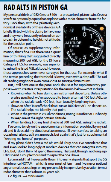
Rad alts are most often found in air-transport aircraft and business jets, but knowing the abs alt can be critical in helicopters and remains useful in light aircraft. (See sidebar for how Editor Frank Bowlin uses the rad alt in his Cessna 340.)
The automated flight control systems (AFCS) use abs alt to execute the flare for landing in Category III automatic (hands-off) landings. Likewise, the autothrottle uses abs alt to initiate the movement of the thrust levers (throttles) to idle on landing.
On most turbine-powered aircraft there are voice altitude callouts on short approach and landing. The abs alt voice callouts not only inform the flight crew of their height, but the cadence of the callouts provides a sense of the vertical velocity in the round out and flare.
Because the localizer and glideslope become more sensitive closer to the runway, some AFCSs use abs alt to adjust the gain on the pitch and roll outputs. It is used in the ground proximity warning systems as a rate of closure to the terrain. Abs alt is used as a limit in TCAS. It blocks a resolution advisory’s descend command when the maneuver would result in ground contact. It’s also used in heads-up display systems to provide the proper runway perspective (tilt and size) during the approach. It is used in synthetic vision systems similar to what is done with heads-up displays. Helicopter pilots in emergency medical services are heavy users of the “raw data” of the height above ground for hovering and landing in unfamiliar areas. In summary, abs alt from a rad alt is used in a lot of safety-critical places.
Measuring Abs Alt
There are two different methods of directly measuring the height of the aircraft above the ground. The first is the use of a radio altimeter. The second is a radar altimeter.
The radio altimeter broadcasts continuously. It’s a small FM transmitter. Its modulation linearly sweeps through a frequency range starting at a low frequency going to a higher frequency. At the end of the sweep, it starts the process over again. The technical term is FMCW, frequency modulated continuous wave. The power output from the transmitter is low. Depending on the model it ranges from 0.04 to 5 watts. The reflected signal is used to measure the height by subtracting the current frequency being transmitted from what is being received. The subtraction is done in the receiver’s “mixer” and in older units the digital computations were minimal. The larger the swept frequency the higher the resolution.
For a parked aircraft the antennas (one transmit and one receive antenna) will be close to the ground so the transmit frequency going out will match the received frequency and the difference is zero. For illustration purposes, say the radio altimeter was designed so it has a frequency difference of one Hz per foot of altitude or height. If there is a 10 Hz difference between the current transmit frequency and what is being received then the aircraft is ten feet above the ground. If the current frequency being transmitted is 100 Hz above what is being received, the aircraft is 100 feet above the ground, etc.
The radio altimeters are simple and robust and for that reason, they are the predominant type in use in commercial aircraft rather than the pulsed radar altimeters. But, they were designed many years ago and the basic design hasn’t changed much since the 1970s.
The radar altimeter is much like weather radar in that it sends out a pulse that is reflected back to a receiver on the aircraft. The transmitter power for radar altimeters is higher than for radio altimeters. Depending on the model, the peak power ranges from 70 watts to a few hundred watts. Radar altimeters use a single antenna as opposed to two antennas in radio altimeters.
The time delay between the pulse being transmitted and the pulse being received is proportional to the height above the ground. The pulse travels to the ground and back at the speed of light. The receiver starts a timer when the pulse is transmitted and stops the timer when the return echo is received. These altimeters are only used for lower heights usually below 5000 feet.
It appears the manufacturers have left it up to their marketing departments to decide what to call their units. One manufacturer calls theirs a radio altimeter when it is using pulsed radar technology. Another says theirs is a radar altimeter when it is using FMCW technology. Even the FAA doesn’t have a single description. It isn’t much of an issue because both radio and radar altimeters have a common TSO (C-87a) and produce the same reading. The key is if the unit has one coax to one antenna, it is a pulsed radar altimeter. If it has both a transmit and a receive coax to individual antennas, it’s using FMCW to determine the aircraft’s height.
5G Interference
As mentioned, the rad alt designs are dated. The frequency band they use—C band from 4.2 GHz to 4.4 GHz—didn’t have many “neighbors.” The swept-frequency radio altimeters by their nature are broadband and they were not specifically designed to reject strong interference from adjacent channels.
The newest 5G band is from 3.7 to 3.98 GHz. The concern is that 5G transmissions from the cell towers can overload the front end of the rad alt receivers. Plus, there is concern about spurious signals from the 5G transmitters landing directly in the 4.2 to 4.4 GHz band. The 5G transmitters vary their output power depending on the number of simultaneous users, typically varying between 100 watts in urban settings and 500 watts in rural areas.
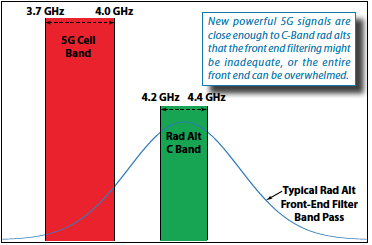 The “front end” of any radio receiver (the first stage after the antenna) has two purposes. The first is to filter out undesired adjacent frequencies and then to amplify the received signal to to a stronger level. This is a common design task even for VOR receivers that must reject relatively close commercial FM broadcast stations.
To faithfully reproduce the input signal at a higher amplitude, the amplifier in the front end should operate linearly. If it becomes overloaded, distorting the signal, several things happen. Intermodulation signals and harmonics are generated. These can cause the frequency coming out of the mixer to be erratic, generating misleading information.
Rad alts have self-checking circuitry but picking up an error due to a strong adjacent transmitter is difficult. If the adjacent signal is strong enough it will saturate the amplifier and completely block the intended signal. If you can’t stop the other guy from transmitting, the way around this overload problem is to add more filtering on the front end. This will increase the attenuation of signals outside the desired band and prevent the overload of the amplifier.
We’ll go deeper into this next month, but it is unlikely the FCC will increase spacing between 5G and the rad alt band. This would require taking back some of the higher frequencies they auctioned off in the 3.7 to 3.98 GHz band. So, when everything settles out, the altimeters will have to tighten up their front end filtering.
When these systems were designed there was no need for a sharp cut-off. The normal filtering on the front end is bell-curve shaped. The peak of the curve is the center desired frequency. As you go on either side of the peak the signal is attenuated. But remember, radio altimeters use a swept FM signal, so the bell curve needs to be wide at the top to accept the swept frequencies being generated from the transmitter. Since it is broad at the top the attenuation is less than if you were operating on a single frequency.
 Can the designers build a filter that is more like a rectangle than a bell curve? Sure, but some modifications may require other design changes. It would also mean retrofitting all existing radio altimeters used in safety-critical conditions. Next month we’ll discuss how we got to this situation and what the future holds.
Now retired, Bob Teter’s career in avionics development spanned over 40 years. During that time he earned his commercial and instrument certs with SEL, MEL as well as becoming a CFI. Today he uses the rad alt in a Boeing 737-800 flying from the right seat while his grandson occupies the left seat of the X-Plane simulator.