Successfully flying instruments requires several ingredients. There are the skills, knowledge, and reflexes developed during training. Varying amounts of technology must be in working order. However, the most fundamental requirement for the existence of IFR flying is literally blind trust. We trust (and hopefully verify whenever possible) ATC to keep us clear of traffic, and we trust our instrument procedures to keep us safe while navigating (it’s a bit harder to verify that one).
Putting this trust into human controllers and procedure designers who are just as fallible as anyone else is no small task, but it is mitigated by the existence of required standardized operating procedures. This doesn’t mean they are always done perfectly, but they statistically provide an acceptable level of safety.
The standards that apply to instrument procedures are commonly referred to as TERPS, which stands for the U.S. Standard for Terminal Instrument Procedures (the title of FAA Order 8260.3). TERPS standards have been modernized over the years, but still bear significant resemblance to when they were first codified in 1966. Today several FAA Orders define the standards related to instrument procedures, and are encompassed by the colloquial term TERPS.
Since we trust our lives to procedures designed to TERPS standards whenever we’re in the soup, let’s pull back the curtain just a little bit to see what’s going on behind the scenes of our approach charts. Note that collectively the TERPS standards easily run over 1000 pages and often involve quite a bit of math, so this is intended to be an overview and is by no means exhaustive. We will be looking at basic concepts and how they apply to approach procedures in this article; in a future article we’ll discuss standards for other phases of flight.
What is TERPS?
The purpose of TERPS criteria is to define the acceptable standards for ensuring flight safety on an instrument procedure, but it generally stops short of addressing how procedures should be designed in practice. Although it does provide some consideration of human factors, flyability, and efficiency, those elements are typically left open to be interpreted by the procedure design specialist. The primary emphasis of TERPS is keeping aircraft a safe distance from the ground and obstacles, so long as a few critical assumptions are satisfied.
The first being that all aircraft systems are functioning normally and that all required navigation systems (on-board the aircraft and otherwise) are performing within acceptable parameters. This means that if you lose an engine and can’t make a required climb gradient, or can’t climb to a required minimum altitude, you’re really on your own for obstacle clearance. The second assumption is that the procedures are based on “a reasonable assessment of the factors which contribute to errors in aircraft navigation and maneuvering.” More on that one in a bit.
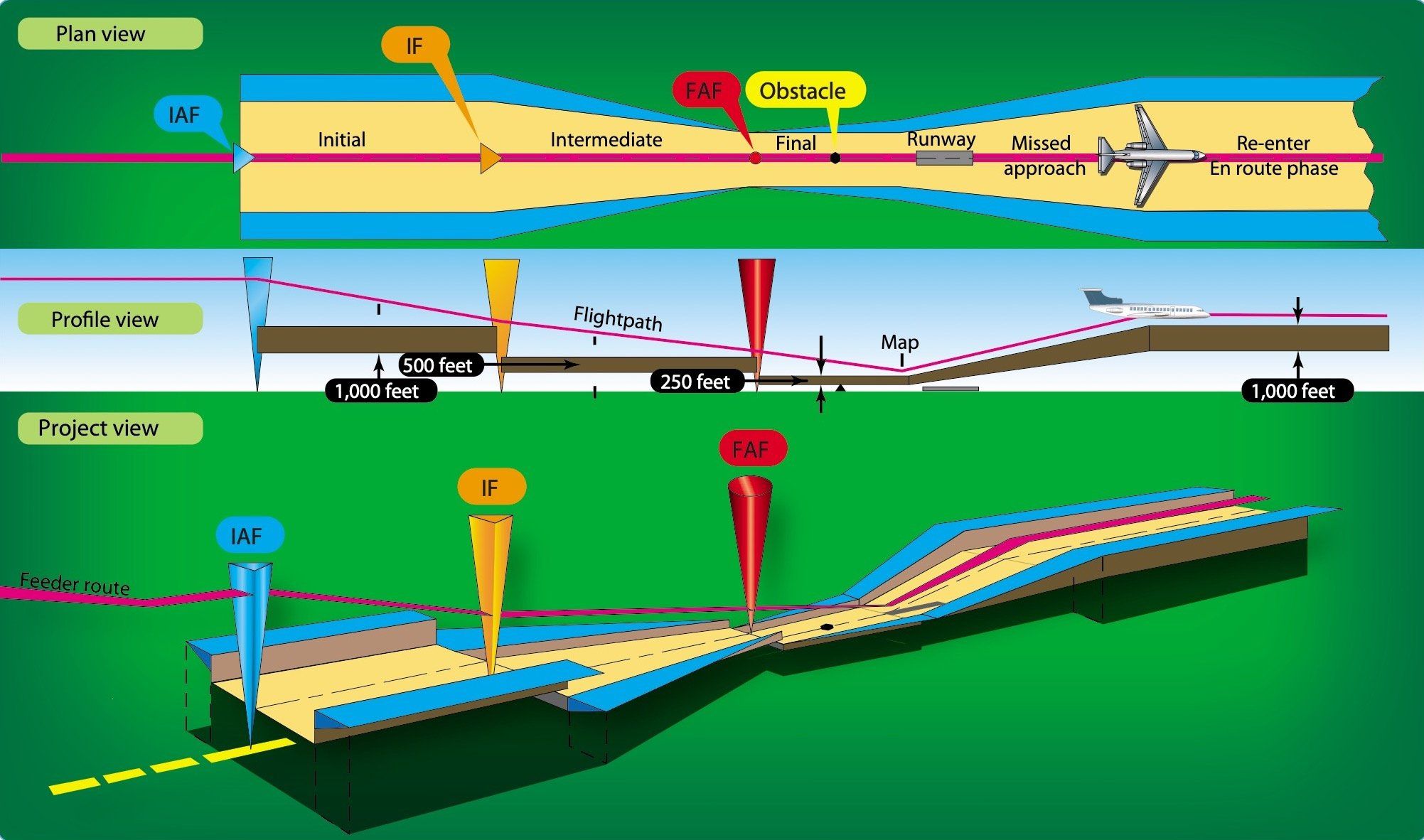
The most fundamental concept of TERPS is required obstacle clearance (ROC). ROC is the minimum amount of obstacle clearance necessary to provide acceptable vertical protection, and it varies for different procedure segments. Level flight segments such as en route, feeder, initial, and intermediate apply a constant amount of ROC. Segments in which aircraft descend with vertical guidance or climb on a departure or missed approach have a sloping ROC surface, with less clearance provided closer to the ground and gradually increasing with distance and/or altitude.
The lateral area in which ROC is applied is known as an obstacle evaluation area (OEA), and the combination of both concepts is the obstacle clearance surface (OCS). An OCS defines a block of airspace that cannot be penetrated by obstacles. The lowest altitude that can be safely flown on a level segment is determined by adding the applicable ROC to the applicable height of the most restrictive obstacle within the segment MEA (known as a controlling obstacle).
OEAs usually consist of a primary area with full ROC provided and a secondary area where ROC diminishes with distance from the segment centerline. From a risk perspective, these areas are designed to provide a high probability of protection against the combined total error induced by pilot behavior, aircraft system performance, and navigation system performance. The result of this is that OEAs cover a fairly wide chunk of sky, but that doesn’t give us an excuse to get sloppy.
Dealing with Uncertainty
Besides your desire for competence and precision, you shouldn’t get sloppy because you don’t know how much of the error budget is already consumed by unknown factors. For instance, a slightly out-of-calibration VOR transmitter error could be compounded by your slightly out-of-calibration VOR receiver (You do your required 30-day checks … right?) and by the signal bending around mountainous terrain. Those combined errors might not leave much room for sloppy piloting.
In some situations, the standard ROC values need to be increased to provide greater obstruction clearance to account for a higher risk of error due to specific conditions. For instance, when a remote altimeter source is used on a procedure, ROC will be increased to account for the chance of differing pressure patterns between the altimeter source and the approach airport. When the remote altimeter is secondary (“When local altimeter not received, use…”) the ROC addition needs to be applied by the pilot when applicable. Another common ROC addition is due to atmospheric effects induced by mountainous areas or rapidly rising terrain.
Another area of uncertainty that is considered in TERPS relates to the accuracy of obstacle locations. If an obstacle is believed to exist in a location that differs from where it actually exists, there is potential for it to not have sufficient ROC applied to it. Each known obstacle has position and height accuracy values associated with it, which means that it can theoretically exist anywhere within those bounds (known as an accuracy cylinder). These reflect the inherent errors of the various survey techniques used to obtain data on each obstacle.
Each procedure segment type has specified horizontal and vertical obstacle accuracy requirements. If the controlling obstacle does not satisfy those requirements, it might necessitate evaluating it in the worst-case location within the accuracy cylinder and/or have its height penalized by its vertical accuracy value. This could, for instance, result in an obstacle with poor horizontal survey accuracy that is believed to be in the secondary area actually be evaluated within the primary area with full ROC applied to it. This could be due to less accurate or unknown survey methods applied decades ago and can be improved by re-survey or even by flight inspection overflight.
There’s also uncertainty about what’s even in the obstacle database and therefore known to procedure designers. Except when fairly close to an airport, obstacles up to 200 feet AGL don’t require FAA notification. If they did, builders and the FAA would drown in evaluations of every building, telephone pole, or cell phone tower in the middle of nowhere. Therefore, to err on the side of caution, in these locations TERPS automatically assumes that there are 200 foot AGL obstacles everywhere, known as adverse assumption obstacles (AAO). In addition, TERPS generally requires that the height of vehicles on roads, railways, ship channels, etc. also be taken into account when evaluating procedures.
Determining Minimums
Designing a procedure generally starts with the final segment, since it can influence much of the remainder of the procedure design. Non-precision final segments are evaluated similar to any other level surface evaluation by applying ROC on top of the applicable height of the controlling obstacle. Placing stepdown fixes can permit lower MDAs once clear of otherwise limiting obstacles. The stepdown MDAs and the altitude at the final approach fix should be calculated at a constant angle to the runway (and that angle is within defined limits).
Determining non-precision minimums is fairly straightforward, but the process is a bit more involved when it comes to vertically guided final segments (ILS, LDA w/GS, LPV, LNAV/VNAV). The angle of the sloping OCS associated with the segment is paired to the pilot’s glidepath angle, and ends at the runway. Since the OCS must be clear of obstacles, this requires different mitigation strategies than a level surface OCS. If an obstacle penetrates the sloping OCS, the glidepath angle can be raised (within limits), but the most common technique is to raise the decision altitude such that it is reached prior to the controlling obstacle. This is because when there is a glidepath, there exists a mathematical relationship between the distance from the runway and the glidepath altitude.
Closely linked to the design of the final segment is the missed approach segment, which is often the most complex part of a procedure design. The missed approach has a sloping OCS, conceptually similar to the vertically guided final segment, except climbing rather than descending. The OCS must be clear of obstacles—a requirement that presents some interesting challenges on a missed approach. The two basic mitigation techniques are to raise the climb gradient (which is generally to be avoided if possible), or to shift the entire OCS vertically to clear the obstacle. This requires changing where the sloping OCS begins by moving the missed approach point or the decision altitude point closer to the final approach fix. This means that you can have higher final minimums due to the need to mitigate missed approach penetrations.
The location of the missed approach point or decision altitude point factors into the determination of the visibility minimums for the approach. As a practical matter, you need to have at least enough visibility to be able to see the runway environment from the MAP or DA point. The height of the MDA or DA is also considered to ensure you have time to descend to the runway. The availability of runway lights can provide some credit to reduce visibility minimums, and visual segment penetrations may result in penalties to the published visibility.

Put into Practice
The final artifact of the instrument procedure design process is its documentation on official FAA forms. These are textual descriptions of all of the procedural information that pilots see on terminal procedure charts, plus a lot of additional data, and with more precision. These forms are what are used by chart publishers, such as the FAA (charting is a process that is separate from, but related to, procedure design) or Jeppesen to accurately depict the final procedure beginning with a specific chart cycle.
Many of these forms actually have the weight of law. The FAA forms documenting approach procedures and obstacle departure procedures are incorporated by reference into 14 CFR Part 97 Subpart C. A summary of the procedures that are added, cancelled, and updated for a chart cycle is published as a direct-to-final rule in the Federal Register (no comment period due to being routine technical changes).
The actual forms associated with the procedure changes are available on the FAA website (search for “Transmittal Letters”). Note that SID and STAR procedures are primarily established for air traffic purposes and are not part of the rulemaking process (though they still have TERPS-like evaluations and forms).
Are you going to be referencing these forms while setting up for an approach, to ensure you fly with fractional-degree accuracy? We certainly hope not. However, the critical point to take away is that every one of the details that are found on those forms and our approach charts is there for a reason. For instance, if you notice something different about a procedure, such as an ILS that doesn’t have a 200-foot decision height, or a missed approach point some distance from the runway, that should be a cue to you that something is going on behind the scenes.
Hopefully having a little bit of the backstory about how those details are determined and how much obstacle protection you’re afforded will make it easier to blindly trust the procedure next time you’re in the soup, and make you think twice about second guessing it. For a slightly more in-depth overview of TERPS, but still not at the technical level as the FAA Orders, we suggest reviewing the FAA’s Instrument Procedures Handbook.


Most countries use PANS-OPs from ICAO rather than TERPs from the FAA. Also, the FAA is the only country of all the ICAO member nations that provides forms rather than charts in the AIP.
Well Wally, there are two types of counties; those who use ICAO and the one who went to the moon.
Having lost count on how many times I have flown around the world and experienced first hand the good and the bad of aviation.. Old to New PANS-OPS, ICAO, TERPS, inches of Hg, MB’s and metric.. I have no doubt that we “aviators” here in the US, are truly fortunate.. We have an extremely safe and functional system, with plenty of radar (and ADS-B) coverage, ample information resources, and a very reasonable government oversight.. This article adds detail to this exception..
This article as Wally can tell you is only an introduction to TERPS, TERPS has a whole of meat to chew on when digging into it. And can be quite interesting.
A fellow BT’er