As a technician, I think of EFIS in terms of failures. While most pilots don’t need to dig deep into system schematics, a little tech savvy can help you recognize and understand the implications of a failed EFIS.
It doesn’t matter if it’s a component failure, wiring problem or software glitch—a proper understanding of the system you fly means learning the architecture as a whole. This means dissecting the interface down to the component level and basic interconnect flow.
Retrofit Glass
It’s easy to incorrectly assume that one brand works like another. While each system displays similar data, how they get that data and the potential single points of failure can be quite different.
Consider the experienced pilot of a Piper Meridian with Avidyne’s Entegra glass cockpit who asked for help understanding a multi-screen, Aspen-equipped Cessna P210 he was about to ferry across the North Atlantic. Our discussion focused on PFD system failures and how the Aspen differed from the Entegra.
The Meridian’s Entegra has dual PFDs, fed by independent pitot/static systems. One system feeds the pilot’s display while the other feeds the independent screen on the copilot’s panel. That’s a lot of redundancy that is rare in retrofits and smaller aircraft, leaving the pilot vulnerable to a single point of failure.
For instance, even dual screen Aspen systems configured for reversionary fail-safe are both fed from the same pitot/static system. That dual Aspen system has redundant air data computers, dual heading magnetometers and reversionary display operation, but the system is vulnerable to a blockage of the aircraft’s single pitot or static system.
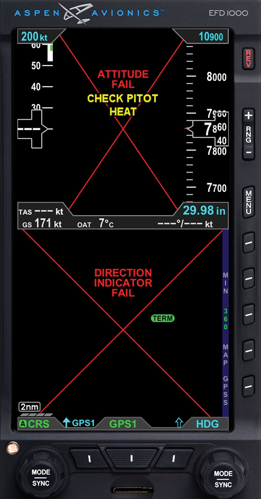
A blocked pitot tube could disrupt the source to the system and remove the airspeed as you’d expect. But to the unsuspecting pilot, like my friend flying the Centurion, pitot or static failures can also deep-six not just airspeed and altitude, but the seemingly unrelated heading and attitude displays as well. (Aspen is working on a way around this illogical single-point failure mode.)
Garmin’s G600/500 PFD, with remote and independent air data, heading and attitude sources, offers no inherent redundancy. If the screen or any of the remote boxes fail, you’re now on the steam-gauge backup instruments and it doesn’t matter if it’s an electrical failure or equipment failure. Either way, you’re left squinting at those strategically placed backup instruments.
This whole idea of a single point of failure for flight instrumentation is certainly not new. In fact, that’s been the norm for light aircraft since the Wright brothers. Our traditional panels with their separate mechanical instruments were one failure of the pitot, static or vacuum system away from a loss of information. But now that failure may have a broader reach, as with the Aspen. Plus there’s vulnerability from having all that information packed into one display that can fail.
Autopilot Interaction
Autopilots are also vulnerable. Garmin’s GAD 43 or Aspen’s EA100 digital attitude gyro emulators are remote boxes that feed the system’s AHRS data to certain autopilots, replacing a spinning gyro, to sharpen the performance on these old analog autopilots. Failures, though, will still cause issues.
Aspen’s flight manual supplement says that if the EA100 feeds the autopilot, a pitot system blockage causes the autopilot to gradually pitch down until the autopilot is manually or automatically disengaged. The red X indication and a “CHECK PITOT HEAT” warning message from the PFD will cause the autopilot to automatically disengage and the autopilot AHRS input to fail.
On the other hand, an Aspen PFD interfaced with the popular S-TEC 55X autopilot has some measure of backup. A single Aspen PFD failure will normally kill the autopilot functions that are sourced from the failed PFD. It’s possible to wire the autopilot’s own GPSS directly to the navigator, bypassing the Aspen. With a failed Aspen, the normal heading and nav tracking would still be unavailable, but the GPS could continue to track the navigator’s flight plan.
A huge hurdle for those new to retrofit PFDs is understanding the autopilot interface. Owners used to mechanical HSIs displaying just VOR/LOC nav course data that later added switchable GPS course data suffered similar growing pains. It’s critical to know what information is being displayed and what data is feeding the autopilot.
Since PFDs have integrated electronic HSIs, those hurdles don’t go away, although on-screen nomenclature, colors and symbology may ease the burden. But PFDs bring additional capabilities that require a thorough understanding to avoid “What’s it doing now?” moments.
Garmin G1000
The G1000 has more parts than most retrofit suites. For the majority of light aircraft with G1000s, this includes two displays, called GDUs. The GDUs are connected together through a high-speed Ethernet data bus. A GDU failure automatically sends primary data to the other screen through the GMA1347 audio panel that serves double-duty as a display hub. The pilot can also manually invoke reversion mode.
Keep in mind that any MFD (including the Aspen) in reversionary mode is somewhat like flying partial panel. The reversionary primary flight data takes the place of the map and supplemental data that’s present on the MFD. If a G1000 display fails, primary flight instruments and engine data are displayed on the remaining screen.
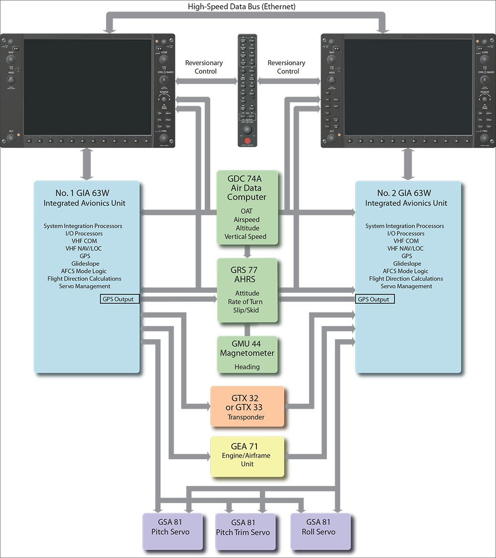
In addition to the GDUs, main players in the G1000 include the GDC 74 air data computer and GRS 77 AHRS for attitude, rate of turn and slip/skid data. Heading comes from the GMU 44 magnetometer. Engine and airframe data comes through the GEA 71, while dual GIA 63 integrated avionics units provide nav, com, and GPS. Some G1000s include the GFC 700 autopilot.
With a failure of the GDC 74 air data computer you lose airspeed, altitude, vertical speed, OAT and true airspeed data. Failure of the GRS 77 AHRS will red-X the attitude with an “attitude fail” message on the display. Failure of the GMU 44 magnetometer fails the heading display.
Fortunately, complete failure of the GEA 71 is uncommon, but will mean loss of all engine instrumentation, including manifold pressure, RPM, oil temperature, EGT/CHT, fuel, vacuum and electrical system data. Individual system probes, which won’t take down the entire system, do fail. A probe failure might show erroneous CHT or EGT temps or no temp at all, depending on the failure.
Like most audio panels, the GMA 347 has a fail-safe emergency mode, which connects the pilot to the primary com radio in the event of a failure. Expect to lose the intercom and all switching capabilities when the audio panel fails, but you won’t go NORDO.
The GFC 700 autopilot will disconnect upon loss of air data, an AHRS malfunction, electrical failure or a failure originating inside the autopilot. Loss of both GPS systems will cause the autopilot and flight director to operate in VOR/LOC mode. Heading command won’t be affected, unless there’s an AHRS or magnetometer failure at the same time.
Read The Supplement
Whether it’s an Aspen, Avidyne or Garmin glass system, factory-installed or retrofit, a pilot who thoroughly understands the interface is better prepared to deal with failure. This includes the autopilot interface, vulnerability of the pitot and static system interface and the limitations of backup systems.
While studying the system’s pilot’s guide, many users fail to recognize that the flight manual supplement is an important source of information, especially concerning failures. In OEM applications, the glass system is incorporated in the aircraft flight manual. But on the retrofit level, shops go through a lot of effort to produce a flight manual supplement that includes normal and emergency procedures, limitations and instructions for continued airworthiness. They’ll also include basic block diagrams to show how the system is interfaced.
I’m amazed at the number of aircraft owners who either misplace this supplement or don’t even know it exists. You wouldn’t operate the aircraft without the flight manual or POH on board and, legally, you can’t operate the aircraft without the flight manual supplements. The supplement, like the flight manual, needs to be available to the flight crew. Keep it handy because when the glass fails it will offer a helping hand in sorting it all out.
Small Glass Can Fail, too
The predecessors of full-on AHRS-driven glass panels were the once-popular electronic HSIs (EHSI) such as the Sandel SN3308 and the Bendix/King KI825. These retrofit boxes take the place of a mechanical HSI, combining the HSI, an RMI and navigation overlays. These all-electric systems are just displays, replacing existing mechanical instruments, but they are not sources of the displayed data. They rely on remote heading gyros plus a remote heading flux sensor, typically the same ones that fed the mechanical HSI.
Although there were alternatives including AHRS packages, the Bendix/King KG102A electric remote gyro package was the dominant choice for these installations. Failure modes of this popular gyro can include frozen heading, erroneous heading or significant precession. In some cases, the EHSI display will X-out the heading data when the heading feed becomes invalid, but the typical installation did not provide a backup.
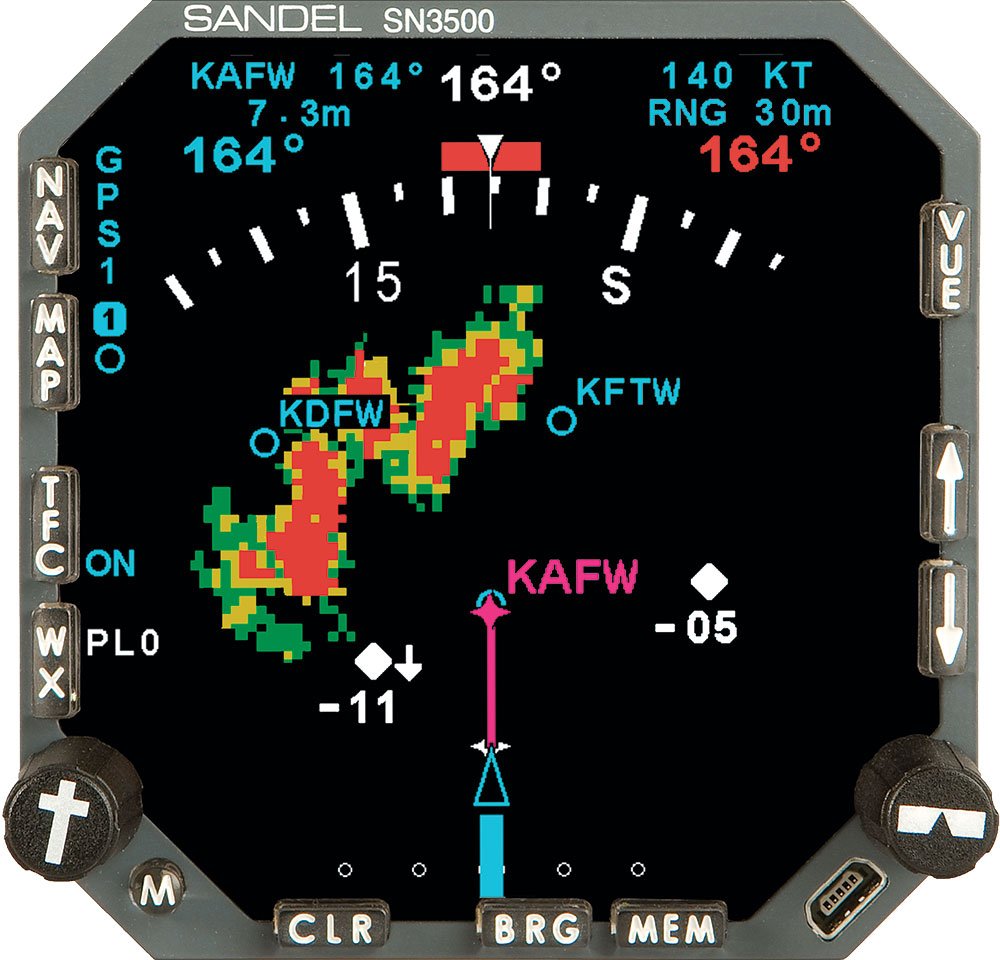
The Sandel SN3308 EHSI requires regular replacement intervals of its internal halogen projector lamp. Removing the unit from the panel may disturb some of the connections, so pay close attention after maintenance. On a maintenance flight I once experienced bogus heading and faulty GPS input because the EHSI wasn’t mated properly with the interface connectors. This is less likely to happen with the later and more robust SN3500 system. —LA
Pay Attention to The X
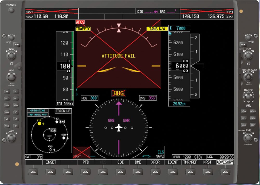
Some pilots, even professionally trained pilots, occasionally do mind-boggling things that increase the likelihood for disaster. One such head shaker was an Avidyne Entegra-equipped Piper Saratoga whose SIMCOM-trained pilot departed into IMC with a misaligned AHRS.
The Avidyne will present a large red X on the attitude portion of the colossal 10.4-inch PFD display until the AHRS is aligned and stable. That’d be tough to miss. In addition, the heading and HSI depiction would be absent from the display. The accident airplane system’s data logging parameters later revealed that the AHRS had failed to align twice previously on the day of the accident.
Note that the accident airplane had—as do all certificated glass-panel installations—a set of backup primary flight instruments that should have provided the information lacking in the failed PFD. Further illustrating this pilot’s lack of understanding of the systems was his attempt to couple the autopilot to this failed AHRS system. Overwhelmed, he confessed to ATC while the airplane flew in circles for several minutes as the situation reached the point of no return.
While analyzing wreckage, investigators found the pitch trim jackscrew in the full nose-down position. The airplane had been descending at 6824 fpm.
There are many lessons to learn from this tragedy, chief of which is the necessity to understand the consequences of a failed system and the impact that failure will have on other systems. Here, the autopilot was no help to a current, instrument-rated pilot who would have been better off hand-flying the steam gauges. Of course, obeying those big red X warnings and staying on the ground in the first place would have been the better choice. —LA
Larry Anglisano is the managing editor of sister magazine Aviation Consumer and is an avionics technician with FAA Repairman certificate.